Struggling with manufacturing errors and communication breakdowns in your CNC machining projects? You provide a detailed design, yet the final part isn’t quite right.
This frustrating cycle of misinterpretation, endless email chains, and production delays eats into your budget and timeline. The core of the problem often lies in the disconnect between your design format and the manufacturer’s interpretation.
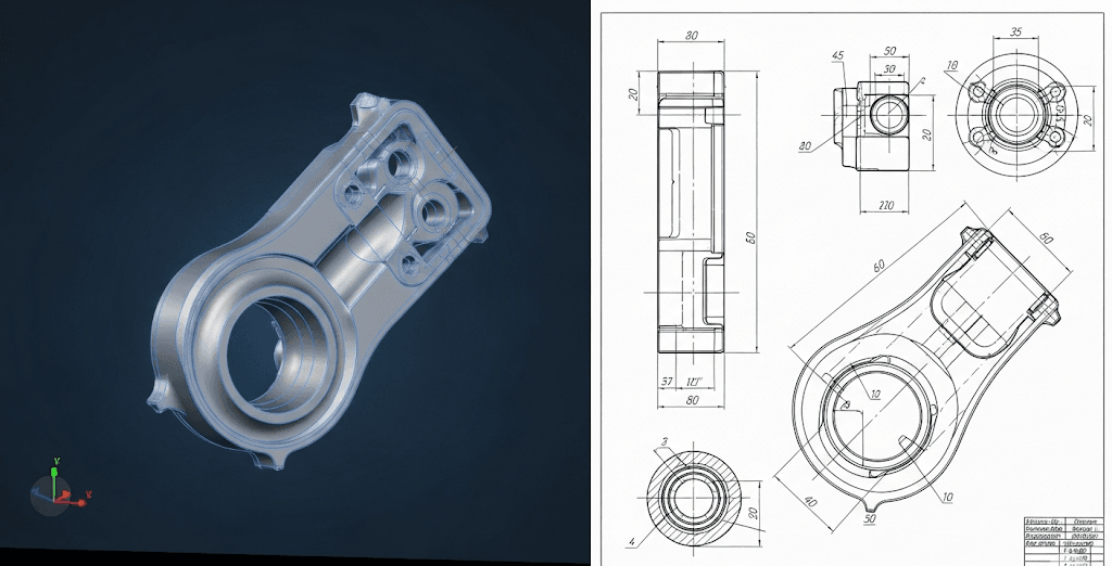
What if you could ensure your design intent is perfectly preserved from screen to machine? The key is understanding the distinct roles and dependencies of 3D models and 2D drawings in the CNC milling process.
For CNC machining, 3D models provide a complete, geometrically unambiguous representation of a part, directly informing the CNC machine’s toolpaths. This significantly reduces the risk of human error. In contrast, 2D drawings require a machinist to interpret multiple views and dimensions, which can lead to discrepancies and communication inefficiencies, though they remain crucial for specifying tolerances, finishes, and other critical information not always embedded in a 3D file.
Choosing the right design documentation is a critical step. Consequently, this decision directly impacts project efficiency, accuracy, and overall cost. As a result, understanding the strengths and weaknesses of both 3D models and 2D drawings is essential for any engineer or product developer. Furthermore, this guide will illuminate the path to selecting the optimal format for your specific CNC milling needs, therefore empowering you to streamline your manufacturing workflow.

3D Models: A Single Source of Truth
3D models offer a holistic view of the part’s geometry. Every curve, hole, and surface is mathematically defined, leaving no room for ambiguity. This inherent completeness makes them a reliable foundation for CNC machining.
With a 3D model, the part you design is the part the machine produces. This direct data transfer minimizes the potential for human error during programming, a frequent issue when working from 2D plans alone. The file itself becomes the standard for your CNC milling project.
2D Drawings: The Interpreter’s Challenge
2D engineering drawings represent a 3D object through a series of flat, orthographic views (top, front, side). While effective for centuries, this method requires the machinist to mentally reconstruct the 3D part.
This interpretation process, however skilled the machinist, introduces risk. A single misread dimension or a misunderstood sectional view can lead to a scrapped part, costing both time and money. The integrity of the information relies heavily on human interpretation.
Clarity in Communication: Bridging the Designer-Machinist Gap
The Efficiency of Visual 3D Communication
A 3D model is a universal language. It transcends verbal or written descriptions, offering an intuitive and interactive representation of the final product. Stakeholders, from engineers to quality control inspectors, can rotate, section, and analyze the model, ensuring everyone shares the same vision.
This clarity accelerates the review process for any CNC machining project. Questions are resolved quickly with visual confirmation, drastically reducing the back-and-forth emails and calls that often plague projects relying solely on 2D documentation. Your CNC milling partner can immediately see your intent.

The Nuances of 2D Drawing Annotations
2D drawings have historically been the vehicle for conveying critical, non-geometric information. This includes GD&T (Geometric Dimensioning and Tolerancing), surface finish requirements, material specifications, and notes on specific treatments.
However, cramming all this data onto a few pages can create a visually cluttered and complex document. Effective communication hinges on the clarity of the drafting and the diligence of the reader. For a successful CNC machining outcome, every note must be seen and understood.
Manufacturing Reliance: From Blueprint to Reality
Direct-to-Machine: The 3D Model Advantage in CNC Milling
Modern CAM (Computer-Aided Manufacturing) software thrives on 3D models. Programmers can directly import the 3D file to generate the toolpaths that guide the CNC machine’s cutters. This seamless workflow is a cornerstone of efficient manufacturing.
The reliance on a 3D model streamlines the entire pre-production process. It allows for advanced simulations to detect potential collisions or machining issues before any material is cut, saving significant resources. For precision CNC milling, the 3D model is the primary driver.

2D Drawings: A Necessary Supporting Role
Even in a 3D-driven workflow, 2D drawings are far from obsolete. They serve as the official contract for inspection and quality control. The detailed callouts for tolerances and finishes on a drawing are often the final arbiter of a part’s acceptability.
At ly-machining, we recognize that a hybrid approach is often the most robust. The 3D model guides the CNC machining, while the 2D drawing provides the critical specifications for final verification and quality assurance, ensuring all aspects of your design are met.
Comparative Analysis: 3D Model vs. 2D Drawing
| Feature | 3D Model | 2D Engineering Drawing |
| Geometric Integrity | High: Unambiguous, single source of truth. | Moderate: Relies on interpretation of multiple views. |
| Communication | High: Intuitive, visual, and interactive. | Moderate: Requires technical literacy to read annotations. |
| CNC Programming | Efficient: Direct import into CAM for toolpath generation. | Labor-intensive: Requires manual data entry and interpretation. |
| Error Potential | Low: Minimizes human interpretation errors. | High: Risk of misreading dimensions or views. |
| Tolerance/Finish Info | Possible with MBD, but not always standard. | Primary method for conveying GD&T and surface specs. |
| Best Use Case | Driving complex CNC milling and machining operations. | Quality control, inspection, and formal specifications. |

The Hybrid Approach: Leveraging the Best of Both Worlds
Why choose one when you can have the strengths of both? The most effective strategy for complex CNC machining projects involves using a 3D model as the primary manufacturing guide and a 2D drawing as the definitive source for all Product and Manufacturing Information (PMI).
This dual-document approach ensures both geometric accuracy and specification compliance. The 3D model tells the machine what to make, and the 2D drawing tells the inspector what to check. It’s a system of checks and balances that leads to superior results in CNC milling. At ly-machining, we are experts in integrating both formats for flawless execution.
![]()
Related Questions
What is Model-Based Definition (MBD)?
Model-Based Definition, or MBD, is an approach where the 3D model is enriched with a comprehensive set of PMI, including GD&T, annotations, and material specifications. This essentially embeds the information from a 2D drawing directly into the 3D file.
MBD aims to create a single, authoritative data package for the entire manufacturing lifecycle. While it represents the future of manufacturing documentation, its adoption requires capable software and knowledgeable partners, like ly-machining, who can work with fully detailed 3D files for CNC machining.
How does file type affect the CNC machining process?
The file type you provide is crucial. Native CAD files (like .SLDPRT or .IPT) and universal 3D formats (like .STEP or .IGES) are preferred for generating CNC milling toolpaths because they contain rich geometric data.
In contrast, mesh files like .STL, while 3D, are made of triangles and are better suited for 3D printing. While they can be used for CNC machining, they often require conversion and can lose some definition. Providing a .STEP file alongside a .PDF drawing is an excellent practice.
Frequently Asked Questions (FAQs)
1. Can I get a quote for CNC machining with just a 2D drawing?
Yes, you can absolutely get a quote with a detailed 2D drawing. Experienced machinists can interpret the views and dimensions to plan the manufacturing process and estimate costs. However, providing a 3D model alongside the drawing typically allows for a faster, more accurate quote and a smoother transition to CNC milling production.
2. What happens if there is a conflict between the 3D model and the 2D drawing?
This is a common concern and highlights the importance of clear documentation. Generally, the 2D drawing is considered the governing document for inspection unless otherwise specified. It’s crucial to have a note on the drawing stating which document takes precedence in case of discrepancies. At ly-machining, we proactively review both files to identify and resolve any conflicts before starting the CNC machining process.
3. Is it more expensive to use a 3D model for manufacturing?
Initially, creating a detailed 3D model might seem like more upfront work. However, in the context of CNC machining, it almost always leads to cost savings. The efficiency gained in programming, reduction in errors, and faster cycle times far outweigh the initial design investment. Using a 3D model streamlines the process, reducing the risk of costly rework and delays associated with misinterpreting 2D drawings.