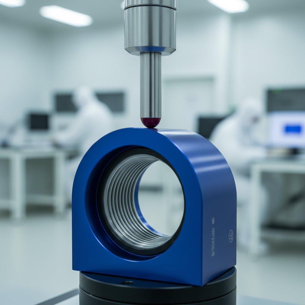
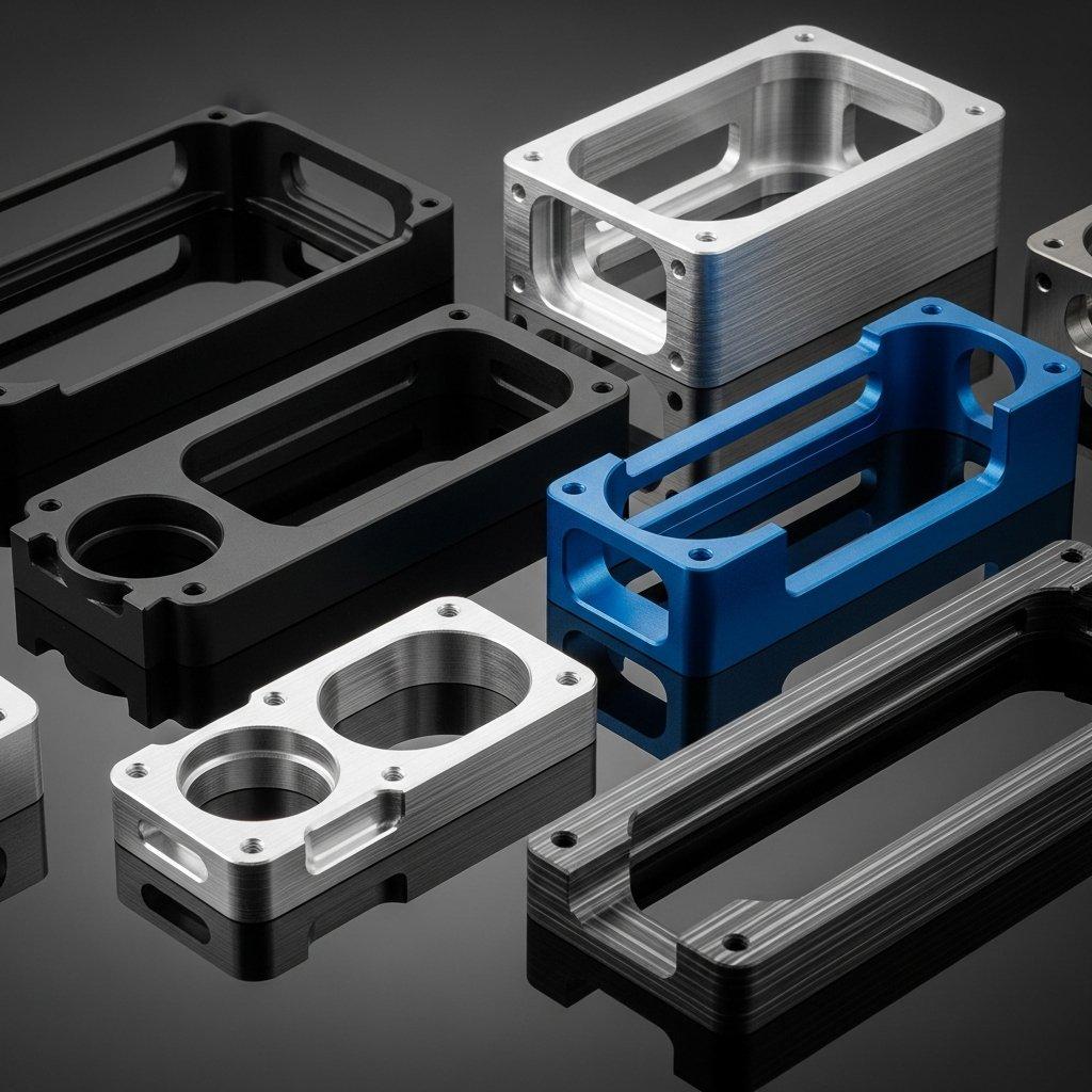
Have you ever sent a detailed drawing for CNC machining, only to receive a part that technically fits the dimensions but fails in its function due to subtle form deviations? You specified the lengths, but what about the straightness or perpendicularity?
This ambiguity often stems from unstated assumptions on a technical drawing. It leads to disputes, costly rework, and project delays. The frustration is immense when a component that should be simple becomes a source of problems, all because of unspoken expectations about precision.
The solution lies in a standardized language of default precision. By specifying a general tolerance like ISO 2768-mk on your drawings, you establish a clear, universally understood baseline for quality, ensuring both dimensional and geometric accuracy for your CNC milling and turning projects.
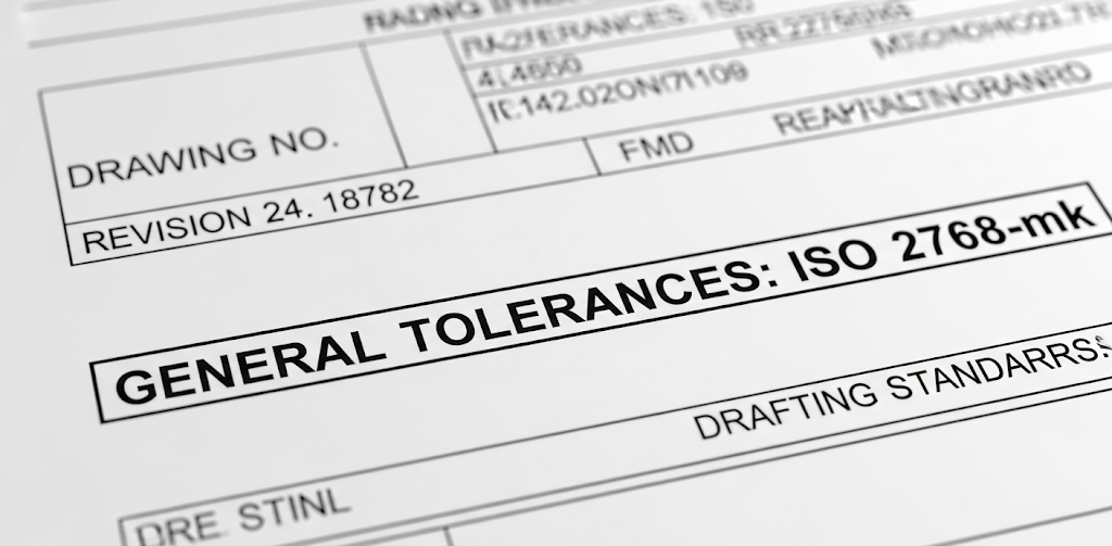
ISO 2768-mk is a standard designation on technical drawings that defines the general tolerances for features that do not have their own specific tolerance indicated. The “m” refers to the “medium” tolerance class for linear and angular dimensions from the ISO 2768-1 standard. The “k” refers to the “K” tolerance class for geometric features like flatness, straightness, and perpendicularity from the ISO 2768-2 standard. Essentially, it provides a default, medium-grade level of precision for CNC machining operations.
Understanding this standard is crucial for anyone involved in product development or manufacturing. Consequently, it acts as a vital communication tool between designers and machinists, creating a shared benchmark for quality. Moreover, by applying this standard, you can effectively prevent misunderstandings and streamline the production process. This guide will therefore break down what ISO 2768-mk means, provide the specific tolerance values, and explain how it impacts your CNC machining projects with a trusted partner like ly-machining.
What is the ISO 2768 Standard?
A Foundation for Simplicity and Clarity
ISO 2768 is an international standard developed to simplify technical drawings. Instead of specifying an individual tolerance for every single dimension and geometric feature, designers can apply a general tolerance. This applies to all features on the drawing that don’t have a specific, overriding tolerance callout.
This practice is fundamental to efficient CNC machining. It makes drawings cleaner, easier to read, and faster to create. For the machinist, it provides a clear baseline level of precision to work towards for non-critical features, whether they are performing CNC milling or CNC turning operations. The standard is divided into two essential parts.
The Two Pillars of ISO 2768
- ISO 2768-1: This part governs general tolerances for linear and angular dimensions. Think of it as controlling the “size” of features—lengths, diameters, radii, and angles.
- ISO 2768-2: This part sets general tolerances for geometrical features. This controls the “form” of a part—its straightness, flatness, perpendicularity, and symmetry.
A drawing can call out one part of the standard without the other, but they are most powerful when used together, as in the case of ISO 2768-mk.
Deconstructing “m” and “k”: The Tolerance Classes
ISO 2768-1 and the “m” for “Medium”
Part 1 of the standard offers four levels of precision for linear and angular dimensions:
- f (fine)
- m (medium)
- c (coarse)
- v (very coarse)
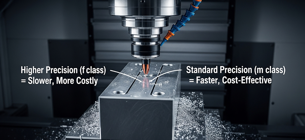
The designation “m” in ISO 2768-mk specifies the medium tolerance class. This is the most commonly used class, providing a good balance between precision and manufacturing cost. It is suitable for a wide range of applications where parts need to fit and function correctly without requiring expensive, high-precision machining on every feature. This balanced approach is ideal for most CNC machining projects.
ISO 2768-2 and the “k” for Geometrical Form
Part 2 of the standard provides three classes for geometrical tolerances:
- H (fine)
- K (medium)
- L (coarse)
The designation “k” in ISO 2768-mk selects the K tolerance class. This class controls the form and orientation of features to a medium degree of accuracy. It ensures that surfaces are reasonably flat and straight, and that features are perpendicular to each other as intended, which is vital for the proper assembly and function of parts produced by CNC milling and turning.
Tolerance Values for ISO 2768-m (Part 1)
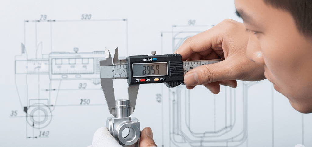
When you specify ISO 2768-m on a drawing, you are instructing the machine shop to adhere to the following permissible deviations for all linear and angular dimensions without a specific tolerance.
Table 1: Permissible Deviations for Linear Dimensions (ISO 2768-m)
| Nominal Length Range (mm) | Permissible Deviation (± mm) |
| 0.5 up to 3 | ±0.1 |
| over 3 up to 6 | ±0.1 |
| over 6 up to 30 | ±0.2 |
| over 30 up to 120 | ±0.3 |
| over 120 up to 400 | ±0.5 |
| over 400 up to 1000 | ±0.8 |
| over 1000 up to 2000 | ±1.2 |
| over 2000 up to 4000 | ±2.0 |
Table 2: Permissible Deviations for External Radii and Chamfer Heights (ISO 2768-m)
| Nominal Length Range (mm) | Permissible Deviation (± mm) |
| 0.5 up to 3 | ±0.2 |
| over 3 up to 6 | ±0.5 |
| over 6 | ±1.0 |
Table 3: Permissible Deviations for Angular Dimensions (ISO 2768-m)
| Nominal Length of the Shorter Side of the Angle (mm) | Permissible Deviation (± degrees and minutes) |
| up to 10 | ±1° |
| over 10 up to 50 | ±0° 30′ |
| over 50 up to 120 | ±0° 20′ |
| over 120 up to 400 | ±0° 10′ |
| over 400 | ±0° 5′ |
Tolerance Values for ISO 2768-k (Part 2)
Adding the “k” invokes the geometric tolerances. This is where the control of a part’s form comes into play, a critical factor in both CNC milling and CNC turning.
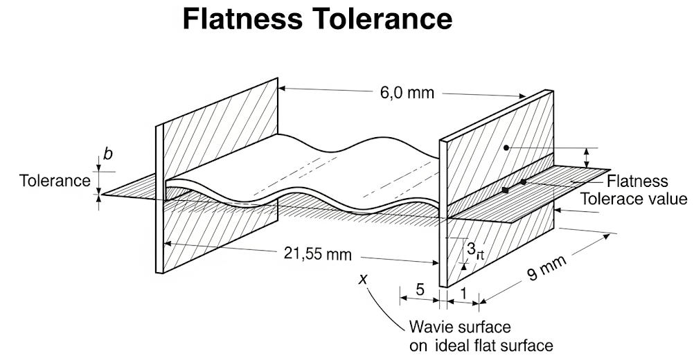
Table 4: General Tolerances for Straightness and Flatness (ISO 2768-k)
| Nominal Length Range (mm) | Tolerance Value (mm) |
| up to 10 | 0.05 |
| over 10 up to 30 | 0.1 |
| over 30 up to 100 | 0.2 |
| over 100 up to 300 | 0.4 |
| over 300 up to 1000 | 0.6 |
| over 1000 up to 3000 | 0.8 |
For flatness, the tolerance is based on the longer lateral surface or the diameter of a circular surface.
For straightness, the tolerance is based on the length of the corresponding line.
Table 5: General Tolerances for Perpendicularity (ISO 2768-k)
| Nominal Length of the Shorter Side (mm) | Tolerance Value (mm) |
| up to 100 | 0.4 |
| over 100 up to 300 | 0.6 |
| over 300 up to 1000 | 0.8 |
| over 1000 up to 3000 | 1.0 |
Perpendicularity tolerance defines how close to a perfect 90° angle two features must be.
The Practical Impact on CNC Machining
Balancing Cost and Quality
Choosing ISO 2768-mk is a strategic decision that balances precision with cost-effectiveness. Requesting finer tolerances (e.g., ISO 2768-fH) on every feature would require more precise machine setups, slower feed rates, additional inspection steps, and potentially specialized tooling. This dramatically increases the cost of CNC machining.
By using the “medium” and “K” classes as a default, you signal that standard, good-quality machining practices are acceptable for the majority of the part’s features. This allows a shop like ly-machining to produce your parts efficiently and economically. You should only apply tighter, specific tolerances (like a GD&T callout) to the truly critical features that directly impact the part’s function or assembly.
Application in CNC Milling and CNC Turning
- In CNC Milling: ISO 2768-mk ensures that milled pockets are sufficiently flat, walls are perpendicular to the base, and the overall dimensions of the block are within a reasonable range. It controls the general form of the part as it is shaped by the cutting tool.
- In CNC Turning: For turned parts, the standard controls the straightness of shafts, the flatness of faces, and the circularity (runout) of diameters. This is crucial for parts that will rotate or fit into bearings. It ensures that a long shaft isn’t bowed and that a faced-off surface is truly perpendicular to the part’s axis.
Related Questions
When should you use a specific tolerance instead of ISO 2768-mk?
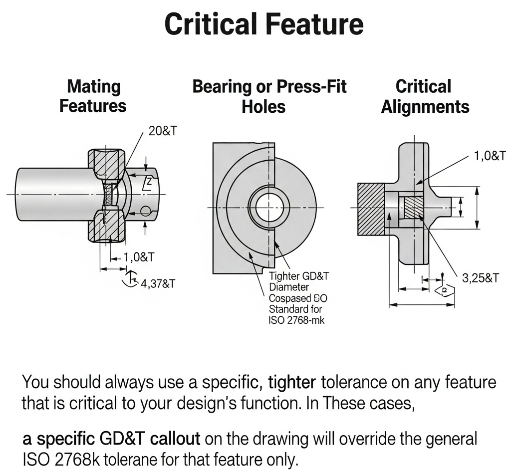
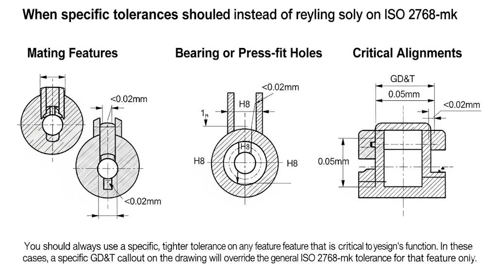
You should always use a specific, tighter tolerance on any feature that is critical to your design’s function. This includes:
- Mating Features: Any surface that fits against another part.
- Bearing or Press-fit Holes: The diameter of holes for bearings or press-fit components requires very tight control.
- Critical Alignments: Features that must be located precisely relative to one another.
In these cases, a specific GD&T callout on the drawing will override the general ISO 2768-mk tolerance for that feature only.
Does ly-machining work to the ISO 2768-mk standard?
Absolutely. At ly-machining, we are fully equipped and experienced in interpreting and manufacturing parts to the ISO 2768-mk standard. Our CNC machining, CNC milling, and CNC turning processes are calibrated to meet these widely accepted benchmarks for quality. When you specify ISO 2768-mk on your drawings, you can be confident that we understand the requirements and will deliver parts that meet this established level of precision and quality.
Frequently Asked Questions (FAQs)
1. What if my drawing doesn’t mention ISO 2768 at all?
If a drawing has no general tolerance callout, it creates ambiguity. A machine shop may have its own internal “standard” tolerances, which might not match your expectations. This can lead to disputes. It is always a best practice to specify a general tolerance standard like ISO 2768-mk to ensure clarity for everyone involved.
2. Can ISO 2768-mk be used for materials other than metal?
Yes, while the standard was developed with metal removal processes like CNC machining in mind, its principles can be applied to parts made from plastics and other materials. However, the designer must consider the properties of the material, as some plastics may be more or less dimensionally stable, potentially affecting the ability to hold certain tolerances.
3. Is “coarse” (c) or “very coarse” (v) tolerance ever a good choice?
Yes, for certain applications. For example, parts for a rough welded frame or non-functional components where appearance and fit are not important could use a “coarse” tolerance. This allows for very fast and inexpensive manufacturing. The choice of tolerance class should always be driven by the part’s function and its assembly requirements.
