Are your CNC machining projects consistently running over budget and behind schedule? Many innovative designs fail to translate efficiently from the screen to the shop floor, leading to costly revisions, unexpected delays, and compromised part quality. The disconnect between design intent and manufacturing reality is a widespread issue that can derail even the most promising projects.
This gap results in endless back-and-forth with your CNC machining supplier, frustrating redesign cycles, and inflated manufacturing costs. Parts that are difficult to machine lead to longer run times, increased tool wear, and a higher scrap rate. Ultimately, a lack of consideration for manufacturability during the design phase erodes profitability and slows your time-to-market, putting you at a competitive disadvantage.
The solution is to integrate Design for Manufacturability (DFM) principles from the very beginning of your design process. By designing parts with the capabilities and limitations of CNC machining in mind, you can drastically reduce costs, accelerate production timelines, and improve the overall quality and consistency of your components. This guide provides actionable DFM strategies to help you optimize your designs for efficient CNC milling and manufacturing.

Design for Manufacturability (DFM) for CNC machining is the engineering practice of designing parts to be as easy and cost-effective to manufacture as possible. Key principles include simplifying geometry, standardizing features like holes and threads, specifying appropriate tolerances, selecting the right materials, and designing features that are easily accessible to standard cutting tools. Applying DFM reduces machining time, lowers costs, and enhances part quality.
With the fundamental challenge and solution established, we can now explore the practical application of these principles. This article will therefore break down the core tenets of DFM as they apply directly to the world of CNC machining. Subsequently, we will examine specific design features, from wall thickness and hole design to tolerances and material selection, providing clear, actionable guidance. Ultimately, mastering these DFM concepts is the key to unlocking more efficient, cost-effective, and successful manufacturing outcomes for your aluminum CNC and other machined parts.
The Core Philosophy of DFM in CNC Machining
Design for Manufacturability is not about compromising your design’s function; it’s about achieving that function in the most intelligent and efficient way possible. For CNC machining, this means creating a part geometry that can be produced with the least number of operations, the simplest tooling, and the fastest cycle times. Every decision, from the choice of material to the radius of an internal corner, has a direct impact on the final cost and production speed.

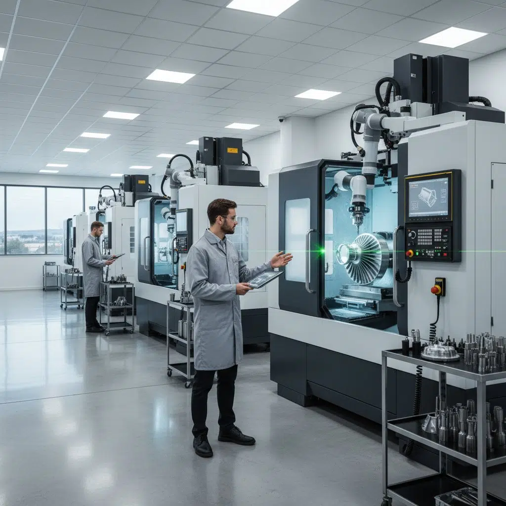
The DFM process fosters a crucial dialogue between designers and the CNC machining experts who will ultimately create the part. At ly-machining, we encourage this collaboration early in the project lifecycle. By reviewing a design before it’s finalized, our engineers can identify potential manufacturing challenges and suggest subtle modifications that can lead to significant savings. This proactive approach prevents costly redesigns down the line and ensures a smoother path from CAD model to finished component.
Applying DFM requires thinking like a machinist. Imagine a block of aluminum inside a CNC milling machine. The cutting tool can only move in certain ways and has a specific shape and size. Can the tool reach every feature you’ve designed? Does it have to be swapped out for a smaller, more fragile tool to create a tiny corner radius? Does the part need to be flipped over and re-fixtured multiple times? Each of these considerations adds time and cost. Effective DFM minimizes these complexities, streamlining the entire CNC machining workflow.

Material Selection: The First DFM Decision
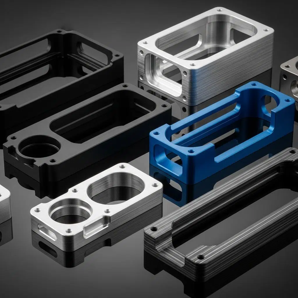
The very first DFM consideration, and one of the most impactful, is material selection. The material you choose dictates not only the part’s physical properties but also its machinability, which is a measure of how easily and quickly it can be cut. A material with high machinability can be processed faster and with less tool wear, directly reducing the cost of CNC machining.
Aluminum is a popular choice for CNC milling for this very reason. Alloys like Aluminum 6061-T6 offer an excellent combination of strength, light weight, and superb machinability. It allows for high-speed cutting and results in a great surface finish, making it a cost-effective default for many applications. Other aluminum alloys, like the 7075 series, offer much higher strength but are tougher and more abrasive, making them more challenging and thus more expensive to machine.
When selecting a material, consider the following DFM questions:
- Does the part truly require the properties of a hard-to-machine exotic alloy, or would a more machinable material like aluminum suffice?
- Can you choose a specific temper or condition of the material that improves its machinability? (e.g., T6 for Aluminum 6061).
- Have you considered the cost of the raw material itself? Sometimes a slightly more expensive but highly machinable material can result in a lower final part cost due to reduced CNC machining time.
The table below provides a general comparison of machinability for common materials used in CNC machining.

Partnering with your CNC machining provider can help you make the optimal choice, balancing performance requirements with manufacturing costs.
Wall Thickness and Ribs: Designing for Stability
A common issue in designs not optimized for CNC machining is having walls that are too thin. Thin walls are prone to vibration and chatter during the CNC milling process, which can lead to a poor surface finish and difficulty holding tight tolerances. They can also warp or deform, both during machining and after, as internal stresses in the material are relieved.
A good DFM rule of thumb is to keep wall thicknesses for metals like aluminum above 0.8mm (0.032 inches). For plastics, a minimum of 1.5mm (0.060 inches) is recommended. If a thin wall is unavoidable, its height-to-thickness ratio becomes important. Tall, thin walls are particularly unstable. You can improve the stiffness of a wall by adding ribs or gussets to the design. These features provide support without adding significant weight or material cost and make the part much easier to machine accurately.
When designing ribs, aim for a thickness at the base of about 50-60% of the main wall thickness to prevent sink marks and stress concentrations. The height of the rib should ideally be no more than three times its thickness. Following these guidelines ensures your aluminum CNC parts are robust and can be manufactured without the challenges associated with part instability.
Hole Design: Simplification is Key
Holes are one of the most common features in CNC machined parts, and optimizing their design offers a significant opportunity for cost savings. The primary DFM principle for holes is standardization. Whenever possible, design with standard drill bit sizes. Using a non-standard hole size requires a custom tool or an interpolation milling operation, both of which add time and cost to the CNC machining process.
The depth of a hole is another critical factor. The deeper the hole relative to its diameter, the more difficult it is to machine. A standard drill can reliably create a hole up to about 3-4 times its diameter. Deeper holes (up to 10x the diameter) are possible but require special “peck drilling” cycles where the drill repeatedly retracts to clear chips, increasing the cycle time. Extremely deep holes require specialized gundrilling equipment and should be avoided unless absolutely necessary.
Also, consider the type of hole bottom. A standard drill bit naturally creates a conical bottom (typically with a 118 or 135-degree angle). Designing a hole with a flat bottom requires a secondary operation with a flat-bottomed end mill. If the function of the hole doesn’t require a perfectly flat bottom, specifying it adds unnecessary cost. For your aluminum CNC components, sticking to standard sizes and reasonable depth-to-diameter ratios will streamline production.

Internal Radii and Corner Design
One of the most fundamental constraints of CNC milling is that cutting tools are round. This means they cannot create perfectly sharp internal corners. Every internal vertical edge in a milled pocket will have a radius equal to the radius of the cutting tool used. This is a critical DFM concept that is often overlooked by designers.
Specifying a sharp internal corner (a radius of 0) is physically impossible to achieve with a standard CNC milling operation. It would require a secondary process like EDM (Electrical Discharge Machining), which dramatically increases the cost. The DFM best practice is to design internal corners with the largest possible radius. A larger radius allows for a larger, more robust cutting tool to be used, which can remove material faster and with less vibration.
A good rule of thumb is to design an inside corner radius that is at least 1/3 of the pocket’s depth. For example, for a 30mm deep pocket, a radius of at least 10mm is ideal. A smaller radius requires a smaller, more fragile tool that is more likely to break and must be run at slower speeds. If your design allows, you can also create “dog-bone” or “T-bone” corners. This involves machining a small circular cutout at each corner, which allows a mating part with sharp corners to fit while still allowing for efficient CNC machining of the pocket itself.
Tolerances: Specifying What Truly Matters
Tolerances define the acceptable deviation for a specific dimension of a part. While tight tolerances are necessary for some critical features, applying them unnecessarily across an entire part is one of the most common and costly DFM mistakes. Every tightened tolerance adds manufacturing cost, often exponentially. This is because holding tighter tolerances requires more precise CNC machining, slower cutting speeds, additional inspection steps, and potentially specialized tooling or grinding operations.
The DFM approach to tolerancing is to specify standard tolerances wherever possible and only apply tighter tolerances to the specific features that absolutely require them, such as mating surfaces, bearing bores, or press-fit locations. For all other non-critical features, using a standard tolerance block (e.g., +/- 0.1mm or 0.005 inches) is the most cost-effective strategy.
When designing an aluminum CNC part, clearly distinguish between critical and non-critical dimensions. Communicate this information to your CNC machining partner, like ly-machining. This allows the machinists to focus their efforts and time on the features that matter most, while efficiently producing the rest of the part. This targeted approach to tolerancing is a hallmark of good DFM and is essential for creating cost-effective, high-quality components.
Threads and Tapped Holes
Threads are another common feature where DFM principles can significantly reduce costs. The most important rule is to use standard thread sizes (e.g., M6, 1/4-20) whenever possible. Using custom or non-standard threads requires expensive, specialized taps or a process called thread milling, which is slower than using a standard tap.
The length of the thread is also a key consideration. A common misconception is that a longer thread engagement is always stronger. In reality, a thread engagement of 1.5 to 2 times the bolt diameter is typically sufficient to create a joint where the bolt will fail before the threads strip in most metals, including aluminum. Designing threads deeper than 3 times the diameter provides no additional strength and significantly increases the risk of tap breakage during manufacturing, which can be a costly failure.
It’s also important to provide sufficient clearance at the bottom of a blind tapped hole. A tap cannot create usable threads all the way to the bottom of a hole. You should design the drilled hole to be deeper than the required thread length to provide clearance for the tap and for chips to accumulate. A good rule of thumb is to make the unthreaded length at the bottom of the hole at least 1/4 of the thread diameter. Applying these DFM guidelines for threads makes your aluminum CNC parts easier and more reliable to produce.

Text and Lettering on Parts
Adding text to a part, such as a logo, part number, or label, is a common requirement. The way this text is designed has a direct impact on CNC machining time and cost. The DFM best practice is to use engraved (recessed) text rather than embossed (raised) text.
Engraved text can be created easily with a simple engraving tool or a small end mill tracing the outlines of the letters. It is a relatively quick operation. Embossed text, on the other hand, is far more expensive to machine. It requires the CNC milling machine to remove all the material around the letters, leaving them standing proud. This is a time-consuming pocketing operation that can dramatically increase the cycle time, especially for complex logos or long strings of text.
When designing engraved text, choose a simple, sans-serif font (like Arial or Helvetica) with a sufficient stroke width. Very fine or ornate fonts require extremely small, fragile tools and are difficult to machine clearly. Also, keep the depth of the engraving shallow; a depth of 0.2mm to 0.4mm is typically sufficient for visibility without adding significant machining time. This approach ensures your part markings are clear and cost-effective.
Choosing the Right CNC Machining Partner for DFM
Implementing DFM principles effectively is a collaborative process. While designers can and should apply these rules, the greatest benefits are realized when working with a CNC machining partner who makes DFM a core part of their service. A proactive manufacturing partner does more than just machine the parts you send them; they act as a consultant to help you optimize them.
When selecting a partner like ly-machining, look for evidence of a DFM-centric approach. Do they offer design reviews or manufacturability feedback as a standard part of their quoting process? Are their engineers accessible and willing to discuss your design to find cost-saving opportunities? A capable partner will have the experience to spot potential issues that a designer might miss and the communication skills to propose effective solutions.
They should be able to discuss the trade-offs between different materials, tolerances, and design features in the context of your specific project goals—whether you are optimizing for cost, speed, or performance. This collaborative relationship transforms the manufacturing process from a simple transaction into a strategic partnership, ensuring your aluminum CNC parts are produced with the highest quality and efficiency.
Related Questions
1. How much cost can DFM really save on a typical CNC machining project? The cost savings from applying DFM can be substantial, often ranging from 10% to 50% or even more on complex parts. Savings come from multiple areas: reduced raw material waste, faster machine cycle times, use of standard tooling, lower labor costs due to fewer setups, and a lower scrap rate. For example, simply changing a design from having multiple, unnecessarily tight tolerances to standard tolerances can cut the part cost in half. Similarly, changing raised text to engraved text could reduce the machining time for that feature by over 90%.
2. At what stage of the design process should DFM be considered? DFM should be considered at the earliest possible stage of the design process, ideally during the initial concept and CAD modeling phase. The cost of making a design change is lowest at the beginning. Making changes after detailed drawings have been created, or worse, after a prototype has been made, is significantly more expensive and time-consuming. Integrating DFM from day one and engaging with your CNC milling partner early ensures that manufacturability is built into the design’s DNA, not bolted on as an afterthought.
Frequently Asked Questions (FAQs)
1. Does applying DFM mean I have to compromise the performance or aesthetics of my part? Not at all. The goal of DFM is not to create a compromised design, but to find the most efficient manufacturing path to achieve the desired performance and aesthetics. Often, DFM changes are subtle—like slightly increasing an internal radius or switching to a standard hole size—and have no negative impact on the part’s function. In many cases, DFM can actually improve a part’s performance by, for example, creating more robust walls or eliminating stress concentrations.
2. My part is very complex. Can DFM principles still be applied? Yes, absolutely. In fact, the more complex the part, the more critical it is to apply DFM principles. For a complex aluminum CNC component, a thorough DFM review can uncover dozens of opportunities for optimization. This could involve breaking a single, monolithic part into a simpler multi-part assembly, adjusting geometries to be accessible to 5-axis CNC milling tools, or identifying features that could be produced more effectively with a different process. Even on the most intricate designs, DFM helps to minimize complexity where it isn’t adding value.
3. Is there a software that can automatically check my design for DFM? Yes, there are DFM analysis tools available, often as plugins for major CAD software packages (like SOLIDWORKS, Inventor, etc.). These tools can automatically analyze a model and flag potential manufacturing issues, such as walls that are too thin, impossible-to-machine internal corners, or non-standard hole sizes. While these tools are very helpful for catching common errors, they are not a substitute for a consultation with an experienced CNC machining engineer. An expert from a provider like ly-machining can provide nuanced feedback and creative solutions that go beyond the capabilities of automated software.