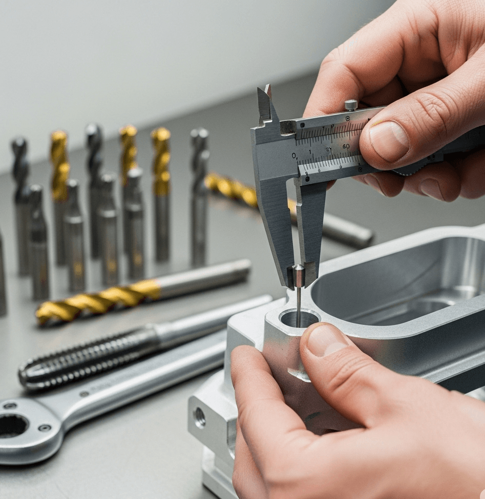
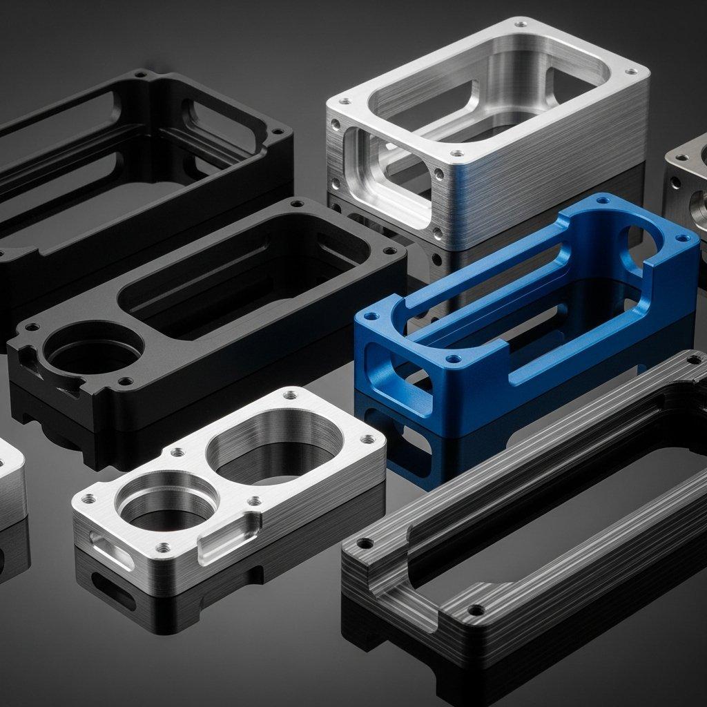
Struggling with fasteners that don’t fit or threads that strip during assembly? Poorly designed tapped holes in your CNC parts often lead to frustrating production delays, increased costs, and compromised joint integrity. This critical design feature, if overlooked, can undermine the quality of your entire CNC machining project.
[ly-machining] offers a clear path to flawless assembly. By mastering the specifics of tapped hole design—from precise depth calculations to selecting the correct size and tolerance—you can ensure robust and reliable CNC parts every time. This guide provides the essential knowledge for perfect threads.
To correctly design a tapped hole for CNC machined parts, you must specify the correct drill size for the desired thread percentage, calculate the appropriate tap drill depth and full thread depth to avoid tool breakage, and define the proper thread class tolerance (e.g., 2B, 6H) based on the application’s required fit and function.
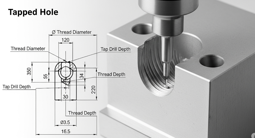
Understanding these parameters is crucial for manufacturability and performance. Therefore, let’s delve deeper into the specific elements that constitute a well-designed tapped hole. Moreover, by applying these principles, you can significantly reduce errors in CNC milling and improve the overall quality of your CNC parts, ensuring a seamless transition from design to production.
Decoding Thread Size and Tap Drill Selection
Choosing the right tap drill size is the foundation of a successful tapped hole. This decision directly impacts the thread engagement percentage, which is crucial for the strength of the screw joint. A common misconception is that 100% thread engagement provides the strongest connection, but this is often not the case.
For most applications, a 75% thread engagement offers an excellent balance between strength and tapping ease. Higher engagement percentages increase the torque required to drive the tap, which elevates the risk of tap breakage, especially in tough materials. Our CNC machining experts at [ly-machining] frequently advise clients on finding this optimal balance.
The formula to calculate the required tap drill size is straightforward:
TapDrillSize=BasicMajorDiameter−ThreadsPerInch(TPI)PercentageofFullThread
Using a standard chart is often the most practical approach. Below is a reference table for common UNC (Unified National Coarse) and UNF (Unified National Fine) threads, showing the standard drill size for approximately 75% thread engagement.
| Thread Size | Threads Per Inch (TPI) | Tap Drill Size |
| #4-40 UNC | 40 | #43 (0.0890″) |
| #6-32 UNC | 32 | #36 (0.1065″) |
| #8-32 UNC | 32 | #29 (0.1360″) |
| #10-24 UNC | 24 | #25 (0.1495″) |
| 1/4″-20 UNC | 20 | #7 (0.2010″) |
| 5/16″-18 UNC | 18 | F (0.2570″) |
| 3/8″-16 UNC | 16 | 5/16″ (0.3125″) |
| #10-32 UNF | 32 | #21 (0.1590″) |
| 1/4″-28 UNF | 28 | #3 (0.2130″) |
Selecting the correct drill is a critical step in CNC milling preparation. An undersized hole will cause the tap to bind and break, while an oversized hole will result in weak, shallow threads that fail under load.

Calculating Optimal Tapped Hole Depth
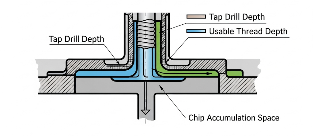
Once the drill size is determined, the next step is defining the hole’s depth. This involves two distinct measurements: the tap drill depth and the required thread depth. It’s essential to drill the initial hole deeper than the required thread length to provide clearance for the tap and for chips generated during the tapping process.
A general rule of thumb is to make the drill depth at least 3-4 pitches deeper than the final thread depth. For a blind hole, the unthreaded portion at the bottom allows chips to accumulate without obstructing the tap, preventing tool breakage and ensuring the creation of clean, complete threads up to the specified depth.
Consider the functional requirements of your CNC parts. The necessary thread depth is typically determined by the length of the mating screw and the material’s strength. A common guideline for thread engagement length in a tapped hole is 1 to 1.5 times the nominal diameter of the screw. For instance, a 1/4″ screw would ideally have 0.25″ to 0.375″ of full, usable thread engagement.
At [ly-machining], we meticulously program our CNC machining centers to control these depths precisely. This precision prevents issues like insufficient thread engagement or “bottoming out” the tap, which can fracture the tool or damage the workpiece. The design must clearly communicate both the thread depth and the overall drill depth.
Understanding Thread Tolerances and Classes of Fit
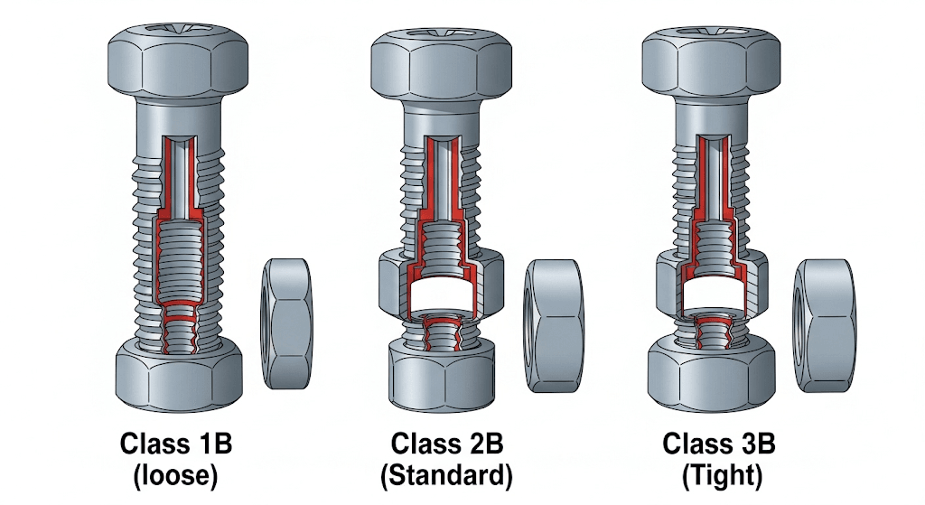
Tolerance is a critical aspect of tapped hole design that dictates the fit between the male (screw) and female (tapped hole) threads. In the Unified Thread Standard (UTS), these fits are defined by thread classes. For internal threads, the common classes are 1B, 2B, and 3B.
- Class 1B: This class provides a loose fit. It is intended for applications where quick and easy assembly and disassembly are more important than precision. You will find it in environments where dirt or debris might be present.
- Class 2B: This is the most common class and offers a medium fit that balances performance, manufacturability, and cost. It is suitable for the vast majority of commercial and industrial CNC parts.
- Class 3B: This class specifies a tight fit, offering minimal clearance. It is used in high-performance, safety-critical applications where close tolerances are necessary to ensure reliability and resist vibration.
The choice of thread class impacts the CNC machining process. Tighter tolerances like 3B may require more precise tooling, such as a “Go” and “No-Go” gauge for inspection, and can increase manufacturing costs. For most CNC milling projects, specifying a Class 2B tolerance is a safe and effective choice unless the application explicitly demands a different fit.
Clear communication of the required thread class on your engineering drawings is essential. This ensures that your CNC machining provider, like [ly-machining], produces parts that meet your exact assembly requirements. A simple note such as “.250-20 UNC-2B” contains all the necessary information: the major diameter, pitch, thread form, and tolerance class.
Material Considerations in Tapped Hole Design
The material of your CNC parts significantly influences the tapping process. Softer materials like aluminum or plastics are easier to tap but are also more prone to thread stripping if over-torqued. Harder materials, such as stainless steel or titanium, require more force to tap and generate more heat, increasing the risk of tool wear and breakage.
When designing tapped holes for different materials, consider these adjustments:
- Hard Materials: For materials like stainless steel, it is often beneficial to specify a slightly larger tap drill size to create a lower thread percentage (around 60-65%). This reduces tapping torque and extends tool life without a significant loss in strength, as the material itself is very strong.
- Soft Materials: In softer materials like aluminum, using a standard 75% thread engagement is usually effective. However, to guard against stripping, you might consider using thread-forming taps instead of cutting taps or incorporating helical coil inserts (like Helicoil) for added durability, especially if the assembly will be repeatedly fastened and unfastened.
Our CNC machining services at [ly-machining] leverage experience with a wide range of materials. We adjust speeds, feeds, and lubrication based on the material to produce high-quality threads consistently. This expertise in CNC milling ensures your design is optimized for both function and manufacturability.
Related Questions
How do you indicate a tapped hole on a technical drawing?
On a technical drawing, a tapped hole is typically specified with a leader line pointing to the hole. The callout note includes the nominal thread size, threads per inch (or pitch), thread series (e.g., UNC, UNF), and the tolerance class (e.g., 2B). For a blind hole, the thread depth and drill depth should also be clearly indicated. For example: 1/4"-20 UNC-2B ↧ 0.50" DRILL ↧ 0.65".
What is the difference between cutting taps and forming taps?
Cutting taps work by shearing material to create threads, producing chips in the process. They are versatile and can be used in most materials. Forming taps (or roll taps) displace material rather than cutting it, creating stronger threads without generating chips. They are ideal for ductile materials like aluminum and copper but are not suitable for brittle materials. The choice affects the required pre-tap drill size.
Frequently Asked Questions
1. What is the most common cause of tap failure in CNC machining?
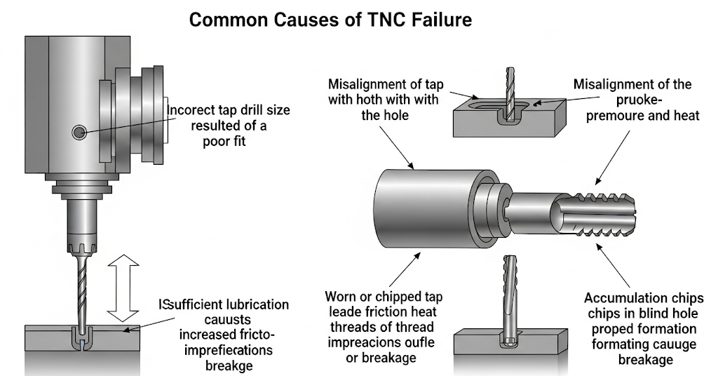
The most frequent cause of tap failure is using the wrong tap drill size, which leads to excessive torque. Other common causes include misalignment of the tap, insufficient lubrication, using a worn or chipped tap, and allowing chips to clog a blind hole. Proper setup and programming in the CNC milling process are essential to prevent these issues.
2. Can you tap a hole that goes all the way through a part?
Yes, this is called a “through hole.” Tapping a through hole is generally easier than a blind hole because chips can exit freely through the bottom, eliminating the risk of chip packing. You do not need to specify a separate drill depth, as the tap will run completely through the part’s thickness.
3. How does thread pitch affect the design of CNC parts?
Thread pitch—the distance between threads—determines the fineness or coarseness of the screw thread. Coarse threads (like UNC) are more common, offering faster assembly and greater tolerance for nicks and dings. Fine threads (like UNF) have higher tensile strength and better resistance to loosening from vibration, making them suitable for precision applications. The choice depends on the specific mechanical requirements of the CNC parts.

