Imagine, for a moment, the utterly catastrophic failure of an optical device—a crucial sight rendered useless, a mission compromised, reputations irrevocably shattered. That chilling prospect, my friends, often begins not on the battlefield, but right here, in the factory, specifically with the CNC machining of the optical scope housing. The problem?
A perilous lack of understanding, or worse, a willful disregard, for the truly indispensable, intricate process steps involved. This isn’t just about cutting metal; it’s about crafting the very soul of optical performance. And without a meticulously executed sequence, designed to anticipate and annihilate risk, your entire endeavor stands on the precipice of failure.

For anyone navigating the precarious terrain of high-precision optical component manufacturing, ignoring the granular detail of the CNC process for optical scope housings is a truly disastrous oversight.
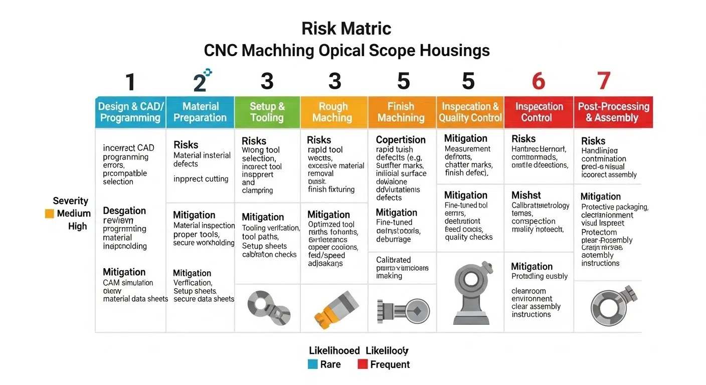
Our Shenzhen facility specializes in these complex challenges, deploying a rigorous seven-step methodology that proactively neutralizes inherent risks, guaranteeing both unparalleled quality and the exact alignment your critical applications demand. We speak from a depth of experience, having witnessed the devastating consequences of cutting corners.
Step 1: Design Review & Material Selection for Scope Housings
Right from the outset, the design review isn’t merely a formality; it is an absolutely foundational truth, an initial bulwark against impending catastrophe. Ignoring this stage, or rushing through it, ensures a cascading series of failures down the line. We must scrutinize every digital facet, every infinitesimal curve, because the geometric complexities of optical scope housings, frankly, forgive no carelessness.
Comprehensive CAD Model Analysis for Optical Precision
One cannot simply load a CAD file and expect miracles; a profound, almost surgical, analysis is imperative. This isn’t just about checking dimensions—though those are, indeed, paramount. It’s about predicting how the material will behave under stress, how thermal expansion will corrupt alignment, and where the structural weaknesses, subtle as they may be, truly lie. To neglect this is to court disaster.
Strategic Material Selection for Optimal Scope Durability
Material selection? This is no trifling matter, no mere commodity choice. It represents the very first, and perhaps most critical, decision in determining the ultimate fate of the optical device. Choose poorly, and the entire project, with its exacting performance mandates, will inevitably crumble. It is an unbelievably foolish mistake to underestimate this pivotal phase.
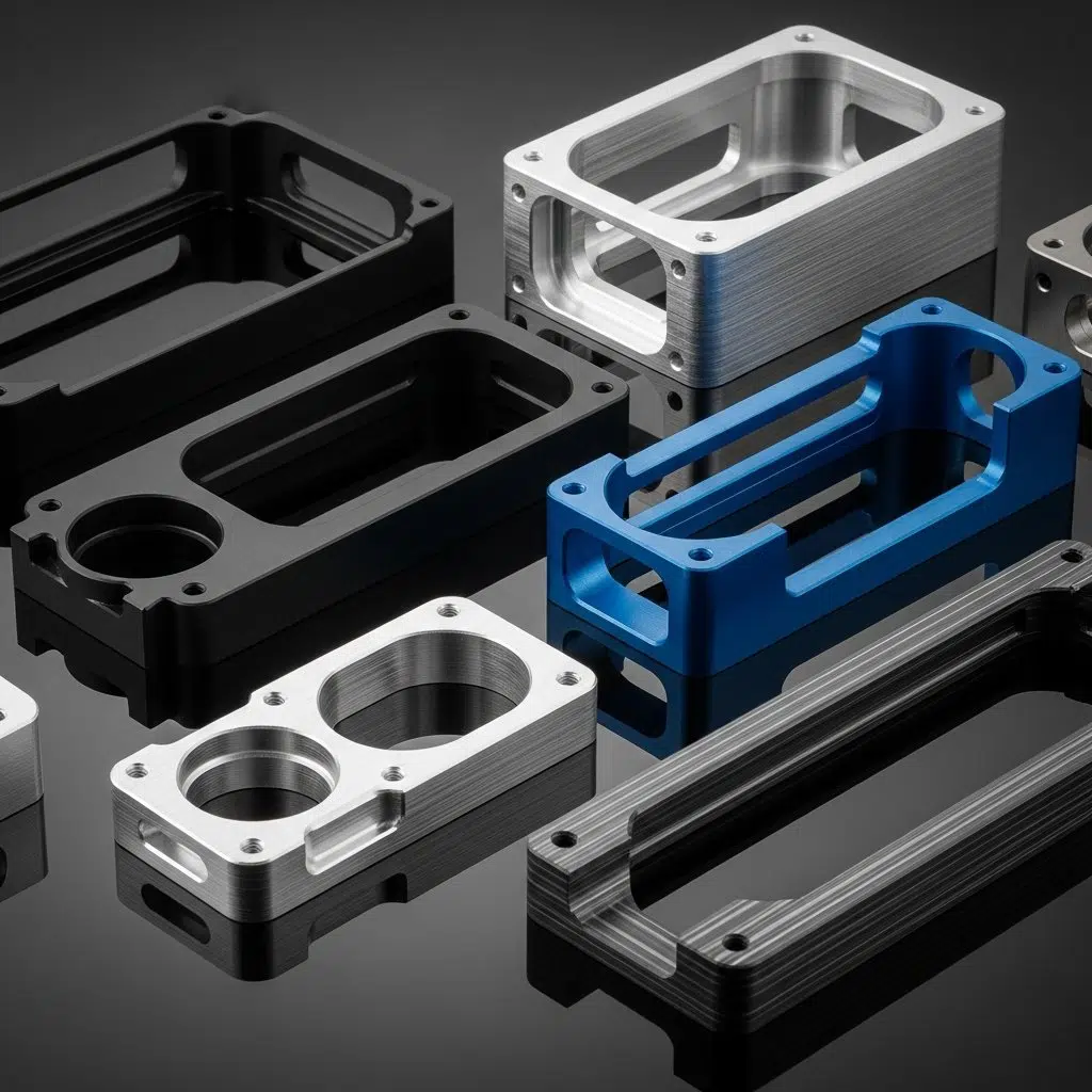
Aluminum Alloys for Lightweight Optical Housings
Aluminum alloys, undeniably, offer a compelling balance of strength and weight—a seductive proposition for many optical applications. But here’s the rub: not all aluminum is created equal, nor will every alloy respond identically to the rigors of multi-axis machining or the subsequent environmental stresses. A seemingly minor miscalculation here leads to warped parts, compromised structural integrity, and ultimately, a product that simply fails to perform.
Thermal Stability & Environmental Resistance Factors
The material’s thermal stability is, for optical applications, an absolutely irreplaceable truth. What happens when your meticulously machined housing expands or contracts with temperature fluctuations? Misalignment. Catastrophic misalignment. Then there’s the relentless assault of environmental resistance—corrosion, oxidation, wear. A flimsy material choice invites premature degradation; it’s an invitation to operational failure, nothing less.

Advanced Fixturing & Custom Tooling Setup for CNC
But really, how can one expect unparalleled precision from the machining process if the very foundation—the fixturing—is unstable? This is where many projects inexplicably falter. The secure, repeatable positioning of delicate optical components is not a suggestion; it is an absolute precondition for success. Any deviation here will propagate errors throughout the entire subsequent process, rendering all other efforts null and void.
Designing Proprietary Fixtures for Secure Optical Machining
Proprietary fixtures are not just a luxury; they are a strategic imperative. Generic clamping mechanisms simply cannot provide the rigidity, the repeatability, or the non-marring engagement required for optical scope housings.
We often observe inadequate fixturing leading to chatter, deformation, and an unacceptably high scrap rate; one might concede that the industry, perhaps, fails to grasp this fundamental reality sometimes.
Specialized Cutting Tool Selection for High-Quality Scope Finishes
Then, the tools themselves! A truly disastrous outcome awaits those who believe any cutting tool will suffice. For optical scope housings, with their often-fragile geometries and demand for pristine surface finishes, generic tools are an unbelievably foolish mistake. The choice of cutter, its geometry, and its coating must be meticulously aligned with both the material and the desired finish.
Micro-Grain Carbide Tools for Fine Features
Consider the microscopic demands of optical features. Micro-grain carbide tools, with their superior hardness and wear resistance, become an absolute necessity.
Attempting to achieve those tight tolerances and mirror-like finishes with anything less is a calamitous gamble. The risk of tool deflection, premature wear, and surface imperfections skyrockets, destroying costly parts in moments.
Optimized Tool Paths for Complex Optical Geometries
Moreover, the tool path isn’t just a trajectory; it’s a meticulously choreographed dance. For complex optical geometries, optimized tool paths are indispensable.
Incorrect sequencing, abrupt changes in direction, or excessive step-overs generate stress, induce chatter, and leave behind an abysmal surface finish. This is a primary cause of rejection, a wholly preventable tragedy if proper planning had occurred.

Step 3: Precision CNC Programming for Optical Scope Housings
Let’s be blunt: a precisely engineered part emerges from impeccably crafted code, not from hope or guesswork. Flawed CNC programming is a silent assassin, lurking in the digital realm, ready to manifest as an expensive, unusable physical component. The risks here are monumental; they encompass everything from material wastage to machine damage, and a complete derailment of production timelines.
CAM Software Programming for Multi-Axis Scope Machining
Modern optical housings demand multi-axis machining, a formidable challenge for CAM software programming. The complexity of managing simultaneous movements across numerous axes, ensuring collision avoidance, and maintaining optimal tool engagement is immense. Any error in this stage, however minor, invariably leads to disastrous gouges, incomplete features, or total part destruction.
Simulation & Verification for Flawless Optical Housing Production
Simulation and verification are not optional steps; they are absolutely mandatory, an unwavering commitment to preventing costly, avoidable mistakes. Skipping this stage is an unbelievably reckless gamble. Catching programming errors in a virtual environment saves not only material but also invaluable machine time and prevents the production of irreparable scrap.
Collision Detection & Material Removal Analysis
The peril of collision detection, or rather, its *absence*, cannot be understated. Imagine a tool crashing into a fixture or, worse, the machine itself! Then there’s the material removal analysis—is the program actually removing material as intended? An inadequate analysis leads to inefficient cutting, excessive tool wear, and a high probability of creating parts that simply do not meet specifications.
Optimizing Cycle Times for CNC Scope Manufacturing
Optimizing cycle times, while seemingly a matter of efficiency, also carries inherent risks. Pushing too aggressively can compromise surface finish, reduce tool life, and increase the likelihood of defects. Finding that delicate balance, preventing both undue delays and compromised quality, is an engineering art; it’s a tightrope walk where a misstep means financial loss.

Step 4: Efficient Roughing Operations in CNC Machining Process
The roughing operation, despite its name, is far from crude; it is a meticulously planned initial assault on the raw material. Underestimate its impact, and the subsequent finishing stages become an insurmountable battle against induced stresses and uneven material distribution. This is where thermal deformation truly begins its malevolent dance.
Strategic Material Removal for Initial Scope Housing Forms
Strategic material removal for initial forms is paramount. Too much too fast, and internal stresses become locked into the part, leading to warpage when finishing cuts are applied. Too little, and cycle times balloon, wasting precious resources. The consequences of an ill-conceived roughing strategy are almost always irreversible, manifesting as a dimensionally unstable component.
Heat Management & Stress Relief During CNC Roughing
Heat management and stress relief are absolutely critical during roughing. Machining generates heat, and excessive, uncontrolled heat can irrevocably alter the material’s microstructure, leading to residual stresses. To ignore this vital aspect is to set a ticking time bomb within the component, one that could affect its long-term performance and stability.
Balancing Speed & Feed Rates for Housing Roughing
Balancing speed and feed rates, in this stage, is a nuanced, high-stakes game. Too fast a feed with insufficient speed leads to heavy tool loads and potential tool breakage—a truly disastrous scenario. Conversely, too slow, and you simply melt material, inducing more heat and stress. It’s a tightrope walk; success hinges on deep, empirically derived expertise.
Cooling Strategies to Maintain Material Integrity
And cooling strategies! They are indispensable, yet often overlooked. Effective coolant application is not merely about lubrication; it’s about rapidly dissipating heat from the cutting zone, maintaining chip evacuation, and preserving the material’s inherent integrity. A failure here is an open invitation for thermal distortion, surface hardening, and tool wear.
Step 5: High-Accuracy Finishing of Optical Scope Housings
Now, the true test of precision: the finishing operations. This stage is unforgiving, demanding absolute mastery. Any errors here—any at all—directly compromise the functional performance of the optical device, rendering all preceding efforts useless. This isn’t just about aesthetics; it’s about the very physics of light.
Achieving Critical Tolerances for Optical Alignment & Fit
Achieving critical tolerances for optical alignment and fit is, frankly, the make-or-break moment. We’re talking microns here, sometimes even sub-micron levels, where the tiniest deviation means total optical failure. A lack of absolute precision leads to image distortion, poor light transmission, and an unusable product; it is an unbelievably foolish mistake to understate this.
Superior Surface Finish Requirements for Scope Performance
The surface finish requirements for scope performance are exceptionally stringent, and for good reason. A rough surface isn’t just unattractive; it causes glare, scatters light, and prevents effective coating adhesion. This can cripple an optical system, regardless of how perfectly aligned its internal elements might be.
Micro-Finishing Techniques for Glare Reduction
Micro-finishing techniques are absolutely necessary for glare reduction. We’re talking about controlled abrasion, burnishing, and specialized polishing that reduce surface roughness to mere nanometers. Without this meticulous attention, internal reflections will degrade image quality, turning a precision instrument into a glorified paperweight.
Maintaining Geometric Dimensioning & Tolerancing (GD&T)
Maintaining Geometric Dimensioning & Tolerancing (GD&T) is not a suggestion; it’s an immutable law in precision manufacturing. Each GD&T callout, no matter how obscure, defines a critical functional relationship. Failure to adhere to these specifications ensures parts that won’t assemble correctly, won’t function as intended, and will generate an astounding volume of scrap. This is a primary cause for profound, operational disappointment.
Step 6: Post-Machining Treatment for Enhanced Scope Durability
The journey isn’t over once the cutting stops; indeed, a new set of perils emerges if post-machining treatments are handled with anything less than utmost diligence. This is where the part’s resilience, its long-term integrity, truly takes root—or, rather, catastrophically fails to.
Meticulous Deburring & Cleaning of CNC Machined Housings
Meticulous deburring and cleaning are not optional chores; they are absolutely indispensable to component reliability. Any residual burr, however minuscule, can dislodge, contaminate optical elements, or interfere with delicate mechanisms. And particulate matter? A single fleck can ruin a lens, making this phase critical, almost sacred.
Specialized Surface Treatments for Optical Scope Protection
Specialized surface treatments are precisely what elevate a mere machined part to a durable, high-performance optical housing. Without them, the component remains vulnerable, exposed to the elements, and inherently susceptible to rapid degradation. This is where longevity is either forged or tragically squandered.
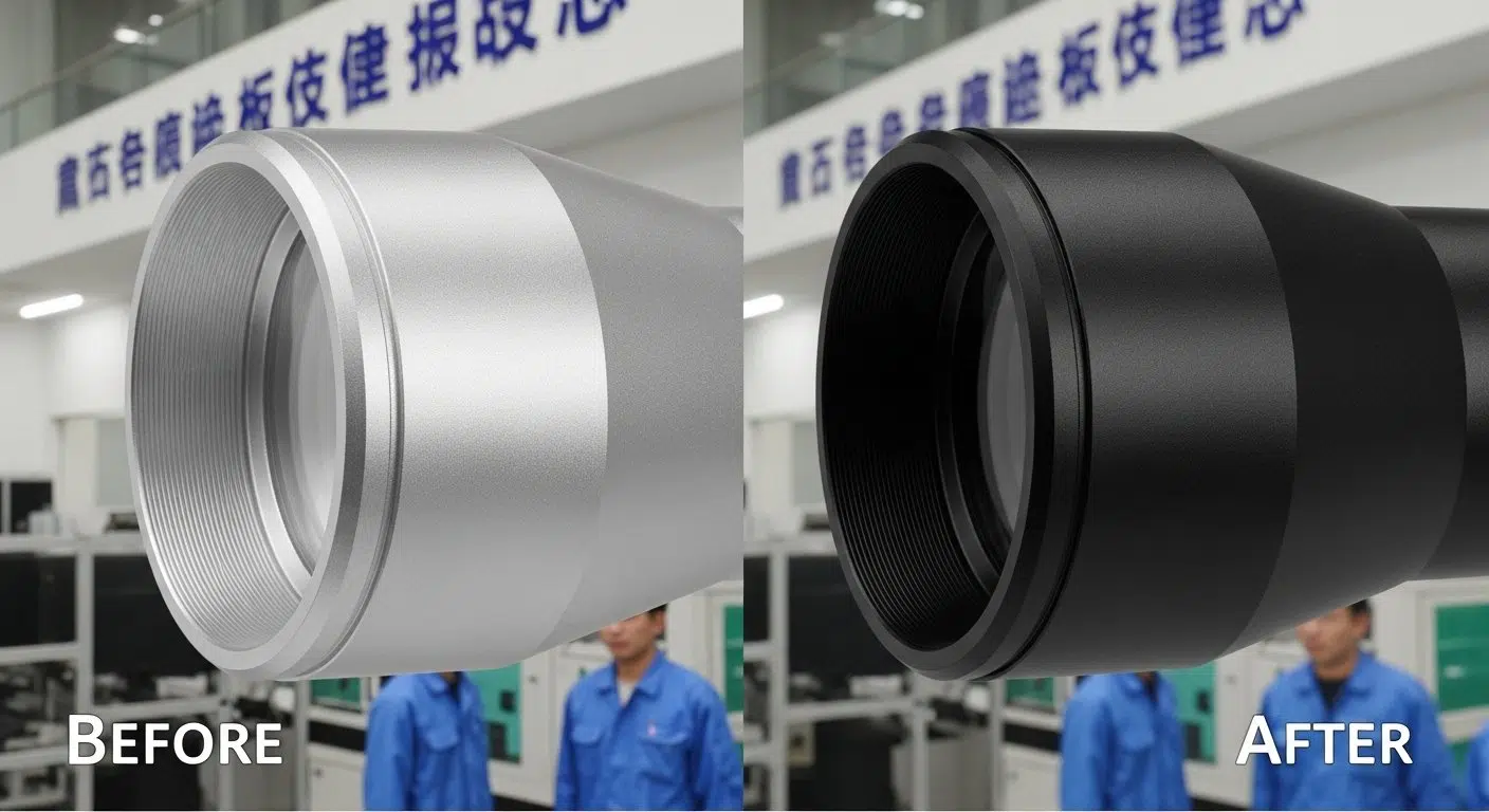
Anodizing for Corrosion Resistance & Aesthetic Finish
Anodizing, for aluminum scope housings, is a quintessential protective measure. It’s not just about color; it’s about creating a hard, corrosion-resistant oxide layer that drastically extends the part’s lifespan. Skipping this step means leaving the raw aluminum exposed, inviting rapid oxidation and a truly disastrous deterioration of both function and appearance.
Chemical Conversion Coatings for Performance Enhancement
Chemical conversion coatings, such as chromate conversion, offer an alternative or supplementary layer of defense, particularly where electrical conductivity or specific adhesive properties are required. To overlook these options is to potentially compromise crucial secondary functions, leaving performance on the table—a wholly avoidable oversight.
Step 7: Rigorous Quality Inspection & Final Assembly of Parts
Honestly, if quality inspection is anything less than rigorous, all prior efforts become a truly disastrous expenditure of time and resources. This final gate is where integrity is either affirmed or where fundamental flaws are—hopefully—exposed before they reach the client, before they irrevocably damage our reputation, before they undermine mission-critical applications.
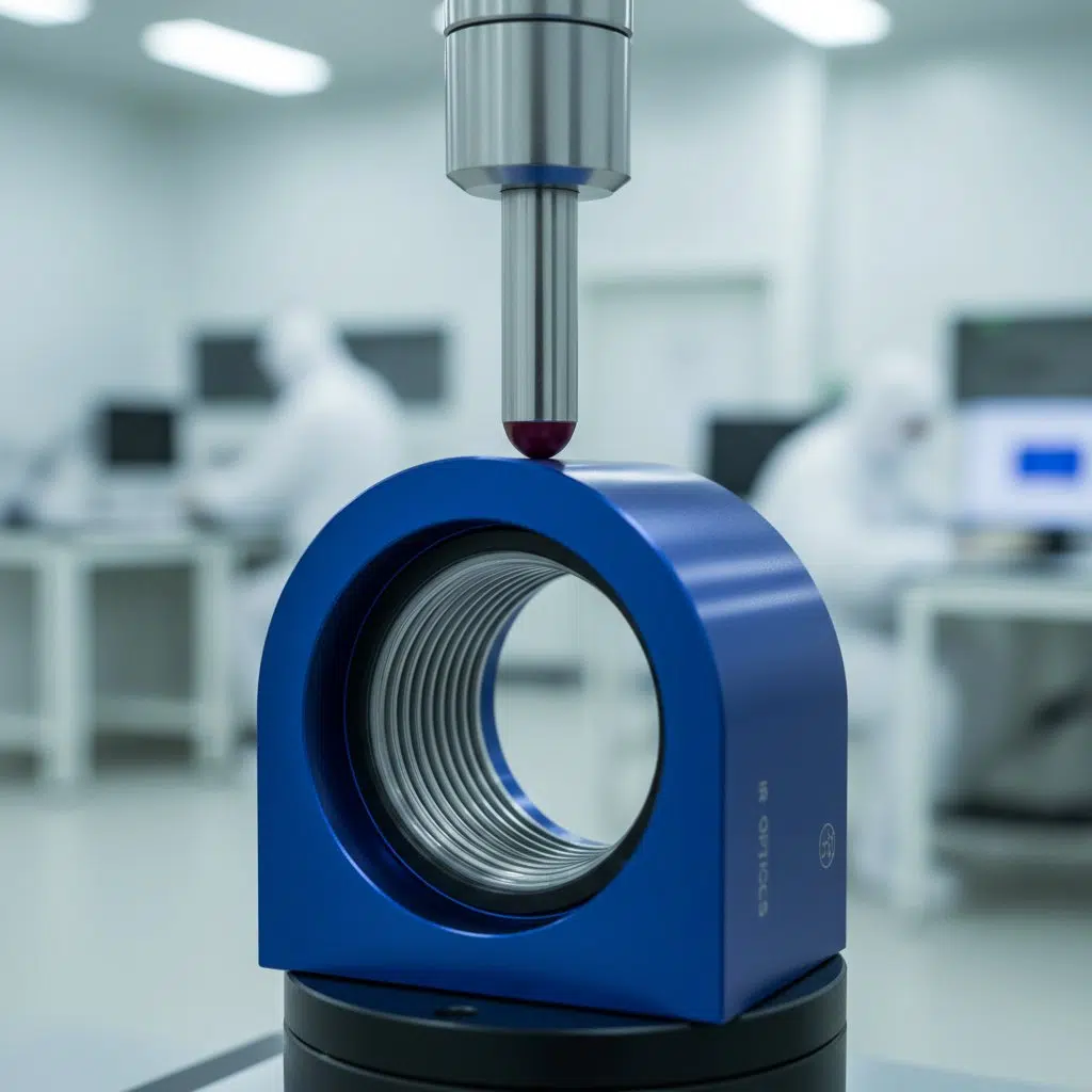
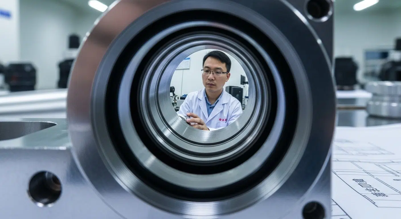
Comprehensive CMM & Optical Inspection of Scope Features
Comprehensive CMM (Coordinate Measuring Machine) and optical inspection are absolutely mandatory—no ifs, ands, or buts. Essential to alignment, the CMM performs its diligent duty. Without these advanced metrology tools, verifying the critical dimensions and geometric accuracy of optical features becomes an exercise in hopeful guesswork, which, one must concede, is utterly unacceptable in this domain.
Functional Testing & Final Assembly for Optimal Performance
Functional testing isn’t merely a checkmark on a form; it’s the ultimate validation. Does the housing truly integrate seamlessly? Does it maintain its integrity under simulated operational loads? Failure here is a direct indictment of the entire preceding process. Then, the final assembly, a delicate dance of precision, must ensure every component fits perfectly, without inducing undue stress.
Verifying Critical Dimensions & Geometric Accuracy
Verifying critical dimensions and geometric accuracy is the paramount concern here. We often find that even minute deviations, those that might pass a less stringent inspection, have disastrous ripple effects on optical performance. This stage, therefore, is where we meticulously hunt down any potential defect, any slight imperfection that could compromise functionality.
Packaging & Delivery Protocols for High-Quality Parts
And the last mile—packaging and delivery! A perfectly machined, meticulously inspected part can still be ruined in transit. Robust, protective packaging protocols are indispensable; they are the final barrier against physical damage, moisture, and contamination. Anything less than exemplary care here is an unbelievably foolish mistake, rendering all prior efforts null. What a calamitous waste, truly.

Case Study: Overcoming Micro-Feature Machining Risks
We once faced a truly formidable challenge: a client required an optical scope housing with an internal micro-feature, an alignment groove just 0.5mm wide with a tolerance of +/- 0.005mm, crucial for light path integrity. Their previous supplier had struggled, consistently producing parts with unacceptable burring and inconsistent groove widths, leading to a truly disastrous 70% rejection rate. The entire project was in jeopardy, and frankly, a calamitous failure loomed.
Our engineering team, after a meticulous design review, immediately identified the primary risk: inadequate tool rigidity and an unoptimized tool path at that incredibly small scale. We designed a proprietary, vacuum-assisted fixture that eliminated micro-vibrations, then developed a custom, single-crystal diamond micro-mill—yes, diamond—specifically for this unique geometry. Our CAM programmers meticulously simulated the process, optimizing speeds and feeds to prevent any tool deflection or material tearing.
The result? Our first batch achieved 100% acceptance, every single part meeting the stringent tolerance. The burring was entirely eliminated, the groove consistency was flawless, and the client, whose project was teetering on the brink of collapse, finally achieved their desired optical performance. This demonstrated not merely our capability, but our absolute commitment to risk mitigation and engineering excellence; it was, in its own way, an inspiring miracle.
The Perils of Underestimating CNC Precision
Look, the reality is this: the seven core steps of CNC machining for optical scope housings are not merely a procedural checklist. Each stage, in isolation, presents a minefield of potential failures, a veritable gauntlet of engineering challenges.
To treat any of these steps with less than absolute, unwavering dedication is to invite catastrophe, to jeopardize the very functionality of your optical device. We, at ly-machining, fundamentally believe that neglecting even one of these phases is an unbelievably foolish mistake, fraught with peril.
Our commitment to rigorous analysis, advanced tooling, meticulous programming, and unwavering quality control is not merely a preference; it is a shield against the inherent risks in precision optical manufacturing. We understand the high stakes involved, the absolutely irreplaceable truth that optical performance hinges on the housing’s integrity. Never must we overlook the potential for failure.
Article Summary: Mitigating Optical Housing Risks
The journey of CNC machining optical scope housings, as detailed across these seven core steps, is fraught with potential pitfalls. From initial design oversights and inadequate material choices to critical errors in fixturing, programming, and finishing, each stage presents substantial risks that can compromise optical precision and durability.
Meticulous post-machining treatments and rigorous quality inspections are absolutely indispensable to avert catastrophic failures, underscoring the imperative for unparalleled technical expertise and an unwavering commitment to process integrity.
Frequently Asked Questions on Optical Housing Machining
Why are custom fixtures critical?
Custom fixtures are absolutely critical because generic clamping methods simply cannot provide the rigidity and repeatability required for the ultra-high precision of optical scope housings. Inadequate fixturing leads to chatter, part deformation, and ultimately, an unacceptably high scrap rate. It’s a fundamental safeguard against pervasive machining errors.
What risks does anodizing mitigate?
Anodizing primarily mitigates the severe risks of corrosion and wear for aluminum optical scope housings. Without this crucial surface treatment, the raw aluminum remains vulnerable, leading to rapid oxidation and a truly disastrous deterioration of both the component’s structural integrity and its aesthetic finish.
How does CMM ensure quality?
The CMM performs its diligent duty by meticulously verifying critical dimensions and geometric accuracy, often to micron-level precision, of the optical scope housing. This comprehensive inspection ensures that all GD&T specifications are met, proactively identifying any minute deviations that could lead to catastrophic optical misalignment or assembly failures.